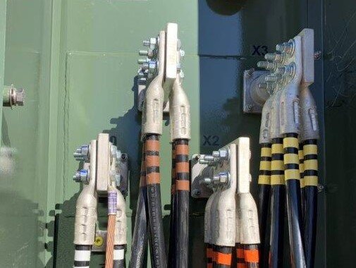
Verifying the Safety of New Electrical Installations
New electrical installations are thoroughly examined and tested to make sure that the power system meets applicable safety standards and all operational goals. Given the variety of equipment and voltage levels required for industrial electrical systems, it’s helpful to be familiar with some of the more common tests. If you work with electrical installations, these methods are familiar to you. For those of you who specialize in other fields, use this summary to learn what to expect in terms of testing and documentation.
Continuity Tests
For a building’s basic electrical infrastructure, continuity tests are a point-to-point check to verify a complete, closed circuit on all cables, outlets, lighting, and control circuits. Multimeters are used to complete continuity testing with circuits (or wires) identified and labeled in the control panel box.
Cable Insulation-Resistance Tests (up to 1000V)
For higher voltages, insulation-resistance tests verify that cable insulation is intact and that there are no voltage leaks that could result in an electrical arc. Megger tests are required for new electrical installations on all power cable up to 1000V. Testing is conducted before the cable is installed to make sure the cable insulation was not damaged in shipping, handling, and storage. Testing is conducted again after the cable is installed but before the cable is connected to power to make sure the insulation was not damaged during installation. All phase-to-phase and phase-to-ground cables are tested.
Cable Insulation-Resistance Tests (over 1000V)
For new installation of medium and high voltage power cable over 1000V, testing and commissioning are completed by an independent, third-party contractor and according to the standards established by the National Electrical Testing Association (NETA). Testing and commissioning are also required for cable recertification of existing installations on a periodic basis. There are several testing methods to choose from. A cable/equipment manufacturer often has a preferred method for testing their equipment. After testing, the third-party contractor provides copies of test reports for the turnover package.
One method for testing medium and high voltage cable insulation is a high-potential test (high pot). A high potential test applies 3-4 times the operating voltage to verify that voltage does not leak through the insulation. This method qualifies and certifies the cable to a manufacturer's standards.
Compared to a high potential test, a Doble test is a less invasive and less destructive method. A Doble test uses direct current (DC) at a minimal voltage to verify cable insulation. An owner may prefer this method if there is a concern that a high potential test may damage older cables or equipment.
Buss Tests
For new electrical installations which contain buss bar, equipment is tested by the manufacturer before it is shipped to the customer. Manufacturer testing documentation can be provided to the customer per factory acceptance tests (FAT). Customers are often present when these FAT tests are conducted. After installation and commissioning, third-party thermal or infrared scans identify hotspots or loose connections. These tests are conducted according to owner requirements.
Ground Resistance Tests
To make sure an entire building is grounded, a minimal ground system resistance test is performed for all ground test weld points according to individual customer specifications.
After Testing and Before Initial Start-up
Before initial start-up to complete commissioning, the electrical contractor performs a visual inspection of the system and equipment. Also, all high voltage terminations, transformers, switchgear, and MCC cubicles are checked and cleaned. These tasks are also documented and results are included in the turnover package to the customer.
Complete electrical installations are within our wheelhouse, and we welcome your questions about how we can help support your needs for new installations or power system upgrades.

